IRIS L-14 Media Briefing
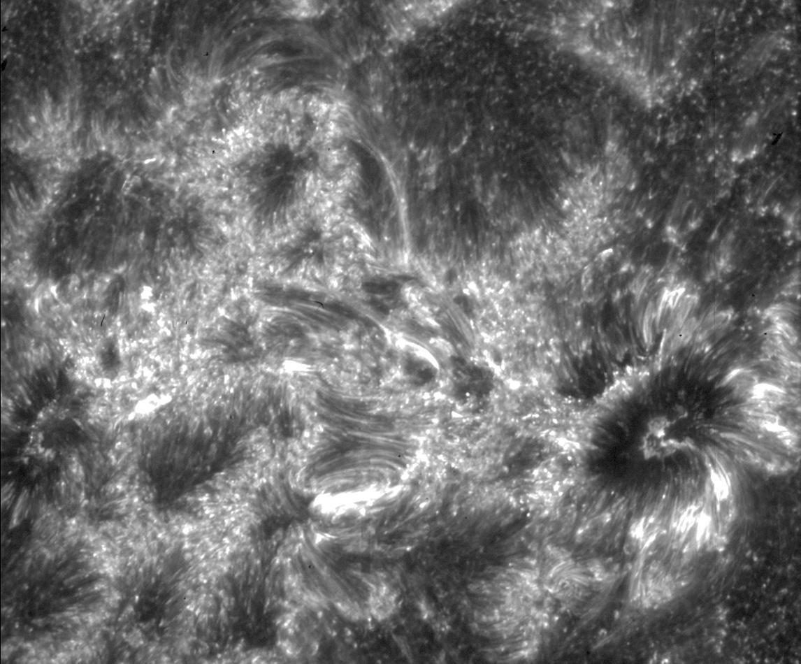
Lying just above the sun's surface is an enigmatic region of the solar atmosphere called the interface region. A relatively thin region, just 3,000 to 6,000 miles thick, it pulses with movement: zones of different temperature and density are scattered throughout, while energy and heat course through the solar material.
Understanding how the energy travels through this region – energy that helps heat the upper layer of the atmosphere, the corona, to temperatures of 1,000,000 kelvins, some thousand times hotter than the sun’s surface itself – is the goal of NASA's Interface Region Imaging Spectrograph, or IRIS, scheduled to launch on June 26, 2013 from California's Vandenberg Air Force Base.
Scientists wish to understand the interface region in exquisite detail, since energy flowing through this region has an effect on so many aspects of near-Earth space. For one thing, despite the intense amount of energy deposited into the interface region, only a fraction leaksthrough, but this fraction drives the solar wind, the constant stream of particles that flows out to fill the entire solar system. The interface region is also the source of most of the sun's ultraviolet emission, which impacts both the near-Earth space environment and Earth's climate.
IRIS's capabilities are uniquely tailored to unravel the interface region by providing both high-resolution images and a kind of data known as spectra, which can see many wavelengths at once. For its high-resolution images, IRIS will capture data on about one percent of the sun at a time. While these are relatively small snapshots, IRIS will be able to see very fine features, as small as 150 miles across.

This image shows the Heliophysics System Observatory (HSO). The HSO utilizes the entire fleet of solar, heliospheric, geospace, and planetary spacecraft as a distributed observatory to discover the larger scale and/or coupled processes at work throughout the complex system that makes up our space environment. The HSO consist of 18 operating missions: Voyager, Geotail, Wind, SOHO, ACE, Cluster, TIMED, RHESSI, TWINS, Hinode, STEREO, THEMIS, AIM, CINDI, IBEX, SDO, ARTEMIS, Van Allen Probes
Credit: NASA
This movie shows images and data from the NASA Explorers Program since the first one Explorer 1 in 1958, through the nobel prize winning COBE, to the newest one to be launched, IRIS. The Explorers Program is the oldest continuous program in NASA . Explorers are one of three flight programs within the Heliophysics portfolio and provide frequent spaceflight opportunities for world-class science investigations for a relatively modest cost.
Credit: NASA
IRIS will advance our understanding of how the enigmatic interface region on the sun powers its dynamic million-degree atmosphere called the corona. IRIS will join the Solar Dynamics Observatory (SDO) which launched in 2010 and NASA/JAXA Hinode (launched in 2006). Together they will explore how the solar atmosphere works and impacts Earth – SDO and Hinode monitoring the solar surface and outer atmosphere, with IRIS watching the region in between. This movie shows a full disk movie of the corona as seen by SDO with movies of the surface of the Sun, called the photosphere, and the chromosphere as seen by Hinode.
Credit: NASA SDO; NASA/JAXA Hinode; GSFC
A sequence of images from the surface to the Corona taken by the Heliospheric and Magnetic Imager (HMI) and Atmospheric Imaging Assembly (AIA) instruments on the Solar Dynamics Observatory (SDO).
Credit: NASA SDO
Jets at the limb seen in the light of Calcium II by the Focal Plane Package on the JAXA/ISAS Hinode Mission.
Credit: JAXA/ISAS Hinode
Jet and plumes near a sunspot near the limb seen in the light of Calcium II by the Focal Plane Package on the JAXA/ISAS Hinode Mission.
Credit: JAXA/ISAS, Hinode
Blinks between and image in He II and an enhanced image. The original image is from AIA on SDO and the enhanced image was created at the LM Solar and Astrophysics Laboratory (LMSAL).
Credit: Dr. Alan Title, LMSAL
A simulation of the Sun in UV light. The movie pans from disk center to the limb.
Credit: Prof. Mats Carlsson at Oslo University
A simulation of heating by a jet.
Credit: Dr. Juan Sykora at LMSAL
A simulation of the location of heating in the transition region.
Credit: Prof. Viggo Hansteen University of Oslo
A simulation of the Sun and corresponding spectra in Mg II.
Credit: Prof. Mats Carlsson, University of Oslo
A comparison of IRIS image reconstruction with previous instruments.
Credit: Dr. Bart de Pontieu at LMSAL
This graphic shows the IRIS observatory with the solar arrays removed. The orange section to the left is the spacecraft bus which includes the spacecraft support structure, the command and data handling system, power distribution system, reaction wheels, X- and S-Band communications systems, Li-Ion battery, magnetic torque rods, and electronics for the sun sensors. The section to the right of the spacecraft includes the instrument optics package and electronics, several components of the attitude control system, and the solar arrays. The instrument includes a 20cm telescope optimized for solar observations which feeds a 5 channel imaging spectrograph. The green section is the telescope assembly, the light blue section is the spectrograph, and the dark blue box is the separate instrument electronics box.
Credit: LMSAL, LM ATC
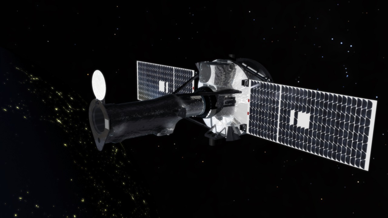
This is a photo of the complete IRIS observatory with the solar arrays deployed. This is taken in a large clean tent at LM prior to vibration testing and prior to installation of the flight MLI blankets. The solar arrays have just been deployed using flight commands.
Credit: LM photo
A second picture of the IRIS observatory. The solar arrays have been stowed in preparation for vibration and shock testing.
Credit: LM Photo
Photo of the instrument optics package prior to instrument level thermal vacuum testing. The section to the left of the white collar is the 20cm solar telescope and the section to the right of the collar is the imaging spectrograph. The spectrograph includes 18 optics used for transmitting the light from the telescope through the 4 channels to the focal planes as shown in the next sequence of images. On top of the telescope assembly is the smaller guide telescope which provides the pointing signal to the secondary mirror of the telescope and to the attitude control system in the spacecraft. The white collar is the primary mirror radiator used to reject the solar thermal load.
Credit: LM Photo
The optical portion of the instrument and the light paths from the primary and secondary mirror of the telescope assembly into the spectrograph. The spectrograph then breaks the light into 2 Near Ultra Violet (NUV)(2785A – 2835A) and 2 Far Ultra-violet (FUV) (1332A-1406A) and one imaging channel.
Credit: LMSAL
These series of photos show the fabrication of the bus structure from a large block of aluminum to the completed bus assembly.
Credit: LM Video
IRIS observatory (without solar arrays) after completion of thermal vacuum and thermal balance testing. Engineers are inspecting the observatory and preparing for transport back to the clean tent for solar array install and final performance testing. A protective cover is on top of the telescope assembly. The vacuum chamber is in the background. Thermal vacuum testing was the last in a series of environmental tests including: vibration testing, pyro-shock (separation) testing, EMI/EMC testing, and thermal vacuum and thermal balance. Optical and system performance tests are carried out throughout the test program to ensure that the observatory meets all of its requirements.
Credit: PM Photo
This video shows the transportation of the IRIS observatory from the thermal vacuum chamber back to the clean tent for final testing and preparations for delivery to the launch site at Vandenberg Air Force Base. The second part of the vide shows the final solar array deployment test. The arrays were released using flight commands. This shows the observatory in its final flight configuration including the MLI blankets. This is how the observatory will appear in orbit with the front of the telescope facing the sun.
Credit: LM Video
These series of photos show the receipt of the observatory at the Orbital processing facility at VAFB. The observatory was received on April 16, 2013 and transferred to its handling fixture and then transferred to a clean tent located at the third stage of the Pegasus rocket. Several photos show the processing of the observatory in the clean tent including the installation of the separation system that mates the observatory to the rocket. The final photos show the Pegasus rocket and the fairings being prepared for installation.
Credit: NASA/Kennedy Space Flight Center
This video clip shows a few team members at the IRIS Mission Operations Center (MOC) preparing for a day of activities. The IRIS MOC, part of the NASA Ames Multi-Mission Operations Center (MMOC), serves as an example of a small, low cost operations shared facility for NASA.
Credit: NASA/Ames Research Center
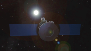
This animation shows the IRIS 620kmx670km, approximate 98 degree inclination, sun-synchronous, polar orbit. Each 97 minute revolution results in 14-15 orbits per day on average and allows for long stretches of uninterrupted or eclipse free solar viewing.
Credit: Analytical Graphics, Inc., STK/Lockheed-Martin/IRIS
This animation shows the initial orbit ground track of the IRIS observatory once it is launched off the western coast of the United States. Communications with the TDRSS allow immediate communications with the Observatory. Within 15-20 minutes, IRIS passes over the McMurdo Ground Station in Antarctica. Approximately one hour after launch IRIS passes over the north pole, Svalbard Ground Station, then shortly afterward communicates with the Alaska Satellite Facility. On the fifth orbit Wallops Ground Station comes into view.
Credit: NASA/IRIS
This animation shows the ground stations and primary facilities used to support the IRIS mission. IRIS collaborates with the Norwegian Space Centre as they provide a science data path for the mission. The NEN or Near Earth Network located at Goddard Space Flight Center provides the central hub for ground station support. Data makes its way to the Mission Operations Center at NASA Ames as science data and images are eventually stored at Stanford. The solar data is then used in multiple ways to benefit society and space exploration.
Credit: NASA/IRIS
This animation provides a look at the tasks the team on the ground perform daily as they prepare for and upload a command set once per weekday. During nominal operations, science and observatory health data are captured daily in a “lights-out” mode. Within six hours, science data is processed and stored at the Science Data Processing facility at Stanford University. A website provides a portal for the public science community to access the data.
Credit: NASA Ames Research Center/IRIS
This animation shows the timeline of activities for the IRIS mission. Following launch, during the initial orbits, the spacecraft “detumbles”, opens the solar arrays, acquires the sun and communicates with the TDRSS and ground stations. For the first thirty days, the instrument and spacecraft are carefully checked and the telescope door is opened on day 21. The science campaign officially begins on day 60 as IRIS begins its exploration of the sun. Nominal daily operations continue for an exciting two year solar mission. After two years, if the observatory is healthy and productive, NASA then has the option to extend science operations.
NASA Ames Research Center/IRIS
Video File for Newsrooms and Editors
Cleanroom b-roll, launch, deploy, and beauty pass animations.
Credits
Please give credit for this item to:
NASA's Goddard Space Flight Center
-
Producer
- Genna Duberstein (USRA)
Release date
This page was originally published on Tuesday, June 4, 2013.
This page was last updated on Wednesday, May 3, 2023 at 1:52 PM EDT.
Missions
This visualization is related to the following missions:Related
- ID: 11314
 Produced Video
 - ID: 11313
 Produced Video
 - ID: 11256
- ID: 11089
 Produced Video